Opening the map: why a framework helps
When you’re planning large-scale co-location of solar arrays and commercial storage, the landscape quickly gets complex — regulatory edges, interconnection studies, and equipment interface rules all matter. A clear framework keeps decisions repeatable and risk visible. In this piece I’ll sketch a stepwise blueprint you can apply across rooftops, car parks, and ground-mount sites, and I’ll point to realistic component choices like a home battery energy storage system when small-scale modularity or hybrid on-site use cases arise. The real-world anchor here is familiar: regional stresses such as California’s heatwave-driven grid strain in 2020 showed how coordinated solar-plus-storage can shift outcomes from rolling outages to managed supply — if integration is done right.
Core principles of the framework
Start with three organizing principles: alignment, interoperability, and operability. Alignment means your business case (peak shaving, demand charge reduction, or market participation) drives system sizing. Interoperability covers functional interfaces — inverter control, communications, and the battery management system (BMS). Operability is the day‑to‑day reality: maintainability, fault isolation, and the human procedures for dispatching capacity. These guide technology selection and the contractual roles among EPCs, O&M providers, and asset managers.
Step 1 — Define the services and boundary conditions
List the grid and commercial services you want the system to provide: load shifting, frequency response, peak shaving, or wholesale market arbitrage. Then pin down limits: site export caps, AC coupling vs DC coupling constraints, and the interconnection agreement’s technical requirements. Early clarity on these items prevents redesigns later. For example, specifying state of charge (SoC) ranges up front avoids redesigning the battery management strategy mid‑deployment.
Step 2 — Modular electrical architecture
Choose an electrical topology that matches scale and redundancy needs. For many commercial wholesale deployments, three‑phase inverters and a distributed string architecture balance reliability and cost. Where building-level loads are balanced across phases, a three phase battery or three‑phase inverter reduces imbalance and simplifies protection coordination. If you want graceful degradation, split storage into multiple independent blocks so one inverter fault doesn’t take the whole asset offline.
Step 3 — Controls and communications
Open, standard communications protocols are a practical must. Use IEC 61850 or Modbus where possible for SCADA/EMS integration, and design for remote firmware updates to keep inverters and the BMS current. Don’t make the controls a black box — insist on documented command sets and simulation modes for pre‑commissioning tests. This reduces commissioning delays and helps you model revenue streams accurately.
Step 4 — Mechanical and thermal considerations
Battery racks, inverter enclosures, and HVAC are often underrated in cost models. Thermal design impacts degradation rates and warranty performance; so does dust and humidity protection. Plan for service access and spare parts staging — nothing slows an asset down faster than having to wait on a replacement inverter during a hot stretch. Also: if you’re co‑locating under shared roofs, consider fire separation and egress requirements early to avoid regulatory back-and-forth.
Step 5 — Commissioning, testing, and operational handoff
Structured commissioning is where theory meets practice. Include test scenarios that mimic expected dispatch patterns and worst‑case grid events. Run integrated tests that exercise the inverter’s anti‑islanding, the BMS fault responses, and EMS logic under partial shading or rapid load changes. A clear handoff package — with O&M manuals, spare parts lists, and a performance baseline — keeps lifecycle costs predictable.
Common mistakes to avoid
Teams often get tripped up by three recurring issues: under‑sizing the communications backbone, assuming ideal phase balance, and overlooking degraded performance curves in warranty calculations. Don’t assume your inverters will handle any arbitrary control signal — verify control envelope limits. Don’t expect perfect phase balance in real sites; plan for imbalance compensation. And always model degradation using conservative depth of discharge (DoD) and cycle life assumptions — warranties rarely cover every real-world stressor. —
Comparing integration approaches — quick pros and cons
Here’s a short checklist to pick between a tightly integrated vs. modular deployment:
- Tightly integrated (single EMS, centralized inverter bank): lower near-term capex, higher single-point risk.
- Modular (multiple inverter‑BMS units): higher redundancy, easier staged build-out, slightly higher per‑kW balance‑of‑system cost.
- Hybrid (central EMS with modular power blocks): best of both worlds if you have proven controls expertise.
Consider your O&M partner’s skillset when choosing — a sophisticated EMS is only valuable if you can operate it.
Metrics that matter when you evaluate suppliers and designs
Measure what can be monetized. Track round‑trip efficiency, warranty‑backed cycle life, and historical availability rates (Uptime %). For wholesale participation, the speed of response (ms-to-second timescale) and dispatch accuracy affect market revenues. Put these metrics into your financial model — a winner on paper but poor in availability is a loser in practice.
Advisory: three golden rules for selecting the right strategy
1) Insist on documented interoperability: require test reports showing your chosen inverters, EMS, and BMS work together under the control signals you’ll use. 2) Price for reliability, not the lowest capital cost: include spare‑unit provisioning and realistic O&M in the LCOE. 3) Build for phased expansion: design electrical and site infrastructure so you can add capacity without reworking the entire interconnection.
Closing reflection and how WHES fits
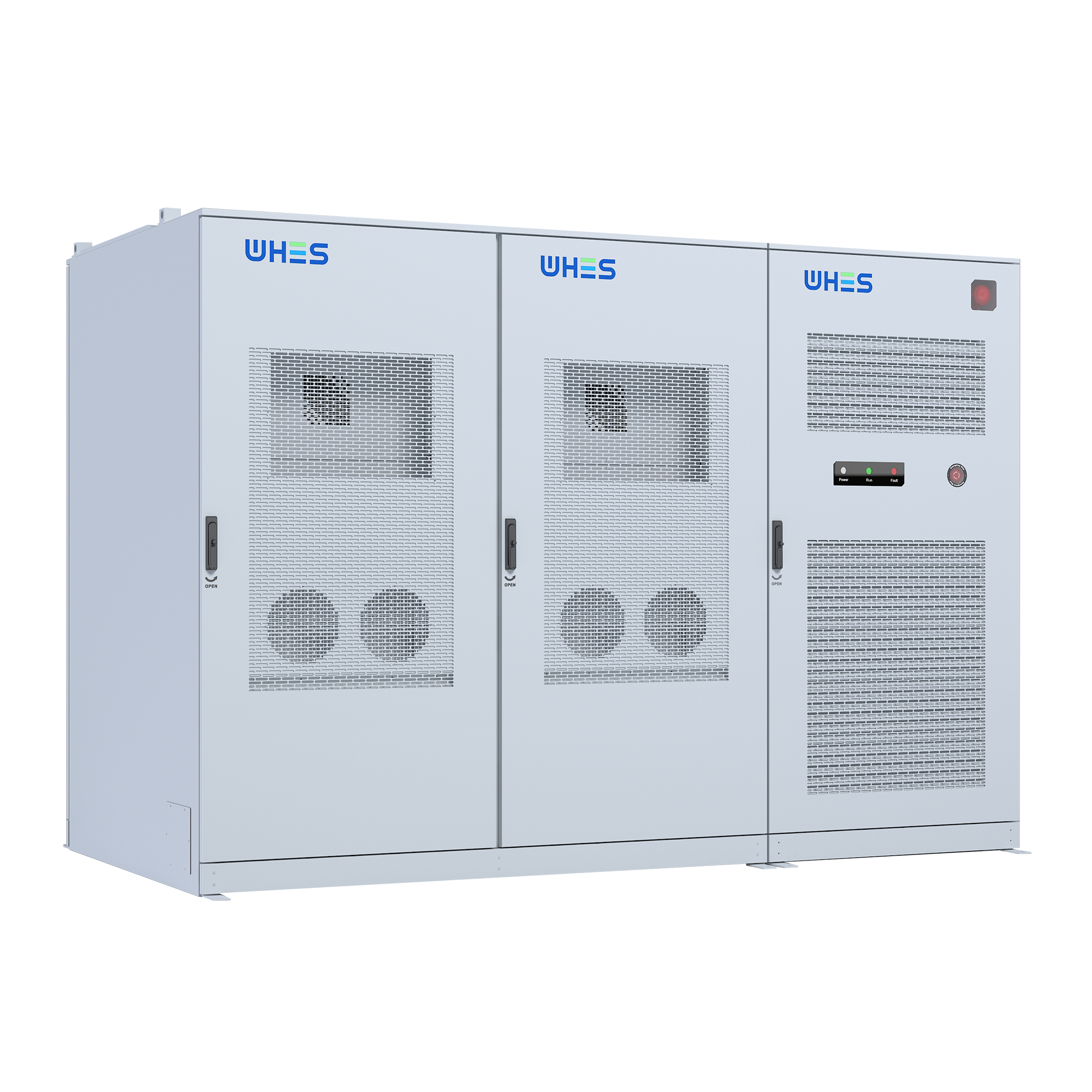
Frameworks are only useful when they’re practical. This blueprint keeps the spotlight on services, interfaces, and operability — which is where projects either shine or stumble. For teams wanting modular, three‑phase‑capable hardware and clear integration pathways, solutions from industrial providers that combine inverter, BMS, and clear control APIs reduce risk and accelerate commissioning; that practical value is exactly the sort of capability WHES brings to project rollouts. WHES.
– practical, tested, repeatable.