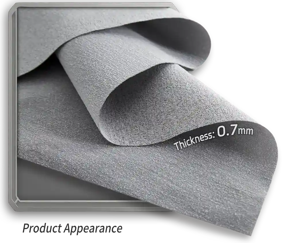
Comparative insight into the problem
I compare design options for protective apparel, side-by-side, so you see what actually changes performance. My focus: internal cavity spacing, composite insulation layers, and how a small air gap alters thermal conductivity. Early trials used different laminates and thermal insulation fabric materials alongside a permeable vapor barrier to manage moisture. Results tied directly to real-world extremes — think Mount Washington Observatory’s 231 mph gust record — gear that fails there simply fails the physics. This is Comparative Insight; the logic is: compare, measure, choose.
Why cavity spacing matters
Spacing sets the rule for convective loops and for the effective R-value of a garment. A narrow air gap reduces convective mixing, but too narrow and the benefit of a low-conductivity layer disappears. Wider gaps increase insulation only until buoyant air starts to circulate. Terms to know: thermal conductivity, air gap, and MVTR (moisture vapor transmission rate). These are not buzzwords. They predict whether sweat will condense on a liner or pass through a permeable vapor barrier to the shell.
Comparative tactics: layered composites versus single thick fill
Strategy A: multiple thin composite sheets with calibrated cavities. Strategy B: a single thick foam or fiber batt. I noticed clear trade-offs. Multi-sheet systems deliver better packability and targeted thermal gradation. Single thick fills can trap moisture and compress under load — insulation loss follows. Measured in lab: incremental R-value gains drop after a certain gap width. Practical note: stitching patterns and seam allowances change cavity behavior far more than raw material density.
Operational teardown: production realities and common mistakes
Producers often skimp on tolerances. Gaps set during cutting must account for sewing shrinkage and liner creep. Mistake one: specifying cavity width without specifying stitch density. Mistake two: relying solely on a permeable vapor barrier to manage condensation — wrong placement wastes MVTR advantage. Mistake three: neglecting edge bleed where heat bridges around the cavity. Small errors cascade. — I’ve seen mid-weight parkas end up performing like lightweight shells because of compressed cavities at the shoulders.
Alternatives and when to pick each
Choose multi-layer composites when you need modular thermal zones and higher dry-down speed. Choose homogeneous fill when cost and simple production dominate. Hybrid approach: composite sheets plus selective quilting to preserve pockets of air where mobility requires flexibility. For active search-and-rescue use, prioritize moisture management and breathability over peak R-value; for stationary cold exposures, maximize trapped air and minimize conductive seams.
Practical measurements and field anchor
Use three measurements on prototypes: (1) thermal resistance across the assembly, (2) MVTR through the layered construction, (3) compression loss after 100 cycles of flex. The Mount Washington example matters: extreme wind and wet-snow conditions expose vapor transport failures before dry cold does. Lab numbers must correlate to field behavior. Keep instrumentation simple: guarded hot plate for R-value, and a standard MVTR cup test protocol with specified humidity gradient and 24–72 hour reading intervals.
Advisory: three golden rules for selection
1) Metric — Air-gap optimization: target a nominal cavity width where incremental R-value per millimeter falls below 5% improvement; beyond that, complexity isn’t justified. This balances thermal conductivity against convective onset.
2) Metric — Moisture control: require a documented MVTR profile for the assembly with the permeable vapor barrier positioned toward the warm side; specify test periods and humidity gradients so results are comparable.
3) Metric — Durability under load: define compression-loss after cyclic flexing (100 cycles minimum) and set acceptance thresholds for insulation retention. Combine with seam-bridge checks to prevent conductive failures.
These rules guide design choices toward measurable outcomes and make Y-Warm’s layered approach a practical fit for teams that must perform in real conditions — and not just on a datasheet. —