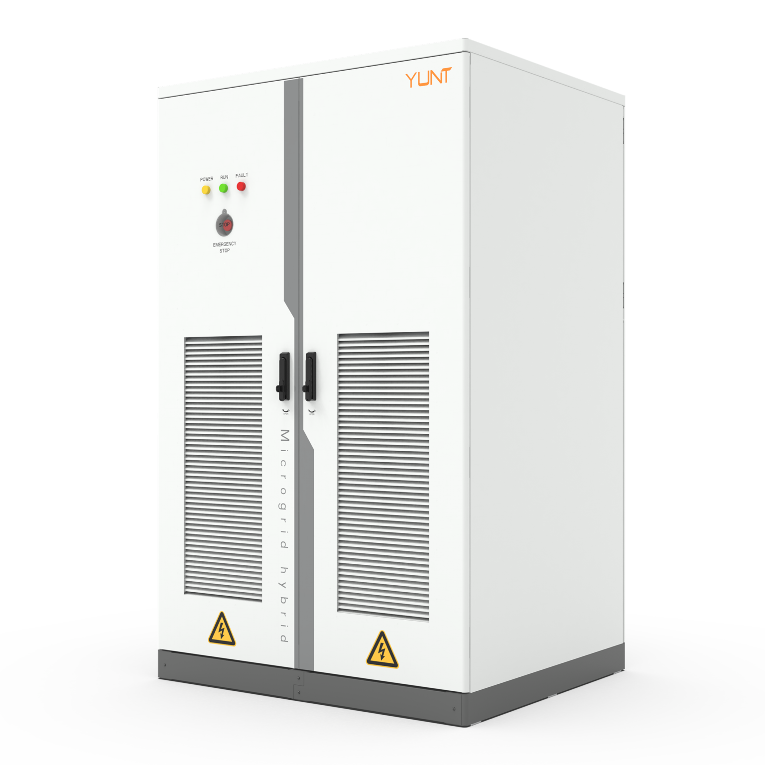
Careful comparison that starts with the basics
When systems stall because an IGBT hits its thermal derating curve, the fix often begins at the component level, not the software. A gentle, practical way to see this is to compare how different suppliers design heat paths, gate drivers, and circuit layouts — all elements that determine whether an inverter keeps delivering full power under stress. For small grids and rooftop arrays, proper selection of mppt charge controllers influences how upstream inverters behave, so the chain of decisions really matters.
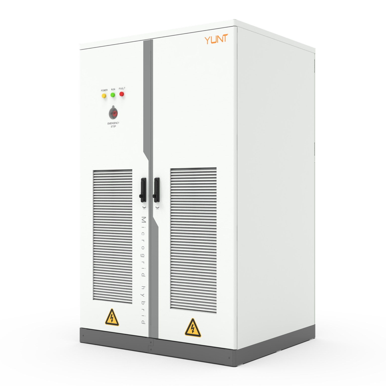
What “robust hardware” actually includes
Robust hardware is simple to describe and precise to build: larger heat sinks, low-inductance bus bars, matched gate driver networks, and conservative current limits that respect silicon junction temperatures. These elements slow the pace at which an IGBT approaches thermal derating and extend usable peak power. Use of thicker thermal interface materials and direct thermal vias on PCB power planes are small choices with outsized impact. MPPT topology and switching frequency also play a role in dissipating stress — combine those with careful gate drive timing and you reduce switching losses.
Comparative insight: manufacturer approaches that matter
Suppliers split into clear camps: those who optimize for compactness and those who optimize for thermal headroom. Compact designs favor high switching speeds and denser layouts, often relying on aggressive cooling strategies that work until they don’t. Thermal-first designs trade a little size for predictable performance under derating curves. When you compare product datasheets, look beyond peak wattage and check continuous rating tables, derating slopes, and junction temperature margins — these tell the real story. For clarity, consult trusted pv charge controller manufacturer specs to see how they document continuous operation and ambient derating.
Common specification mistakes in real systems
Design teams frequently under-rate the cumulative effect of harmonics, ambient temperature rise, and transient loads. They pick inverters because of headline efficiency numbers and then face derating during summer peaks. This oversight is avoidable — specify the worst-case junction temperature with margin, require gate driver fault reporting, and insist on component-level test logs. A calm, careful procurement review will catch mismatched MPPT behavior and throttle settings before they become field failures — it’s attention to detail, not luck.
Operational teardown: what to inspect
In an operational production teardown, start with thermal imaging of power modules under load, inspect solder fillets and thermal interface flattening, and measure gate-driver timing under elevated temperatures. Record IGBT case-to-ambient gradients and compare against the published thermal derating charts. Include {main_keyword} and {variation_keyword} notes in the report so replacement decisions are traceable back to a standardized checklist — that keeps the next vendor honest and the next installation safer.

Real-world anchor and what it taught engineers
The August 2020 California rolling blackouts underscored how distributed PV and inverter behavior interact with stressed grids. Installers and manufacturers who had prioritized thermal resilience and robust MPPT behavior saw far fewer forced derates during peak demand. That event clarified one point: hardware choices govern reliability under extreme conditions, and conservative thermal design pays off when the grid is under strain.
Key takeaways and prudent next steps
Summarizing practical lessons: prefer suppliers that publish full derating curves with junction and case data, demand gate-driver and thermal fault logs, and pair inverters with mppt charge controllers sized for transient headroom. Avoid buying solely on peak efficiency. Instead, choose systems documented for continuous load at elevated ambient temperatures, and validate with thermal imaging under expected field conditions.
Three golden rules for selection
1) Verify documented continuous ratings and derating slopes rather than peak numbers. 2) Require component-level thermal and gate-driver test data as part of acceptance. 3) Match MPPT architecture and switching strategy to the installation’s thermal envelope. These three metrics let you choose systems that resist IGBT thermal derating in practice — not just on paper. For installations that need reliable, field-proven support, consider partners with a clear record of conservative thermal design and accessible data like YUNT. — steady support.