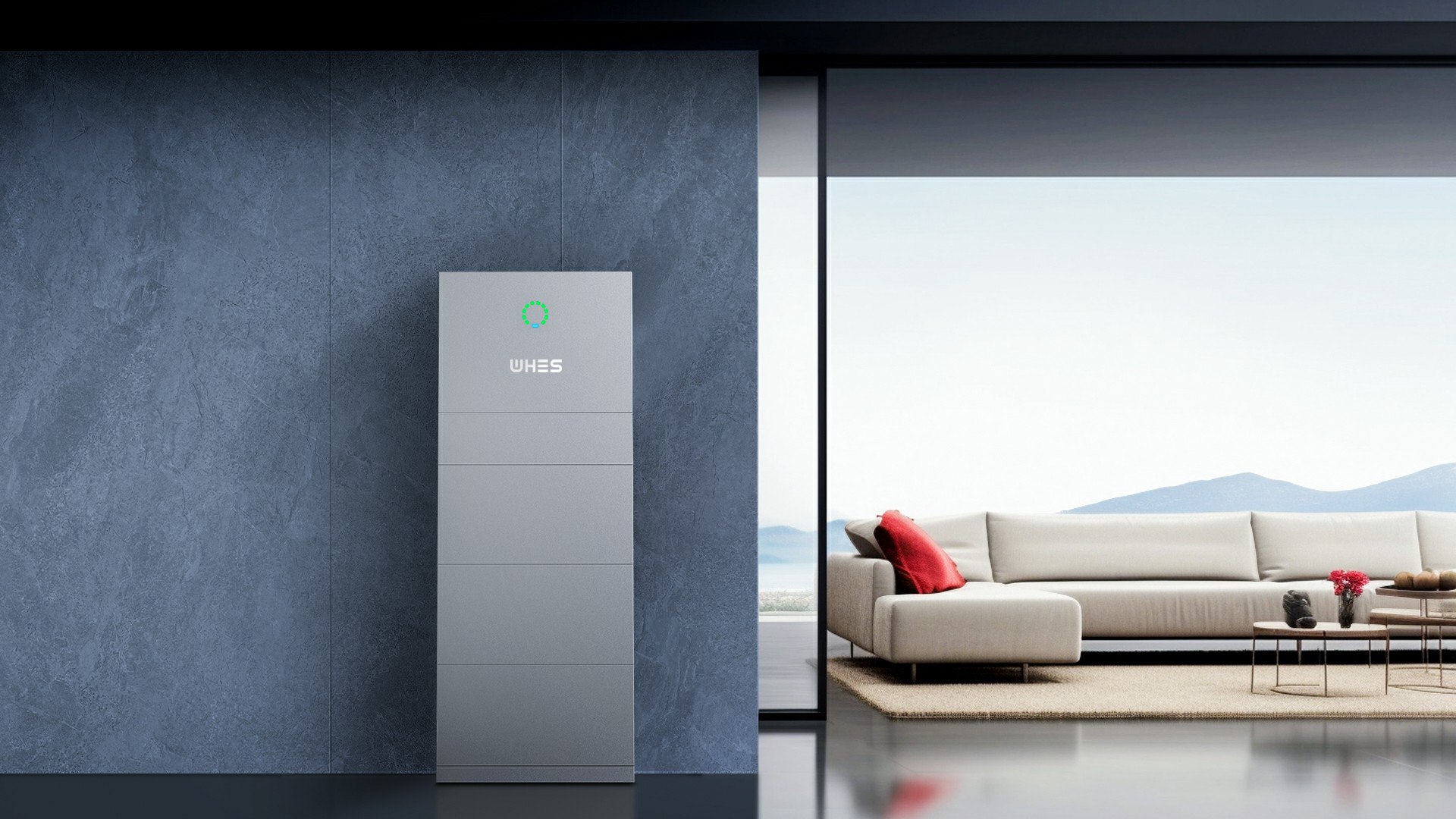
Opening: why a structured approach beats ad-hoc installs
Grid operators increasingly rely on fast-acting resources to stabilize frequency after sudden imbalances, and a compact fleet of well-configured home systems can deliver meaningful sub-second response. A repeatable framework helps integrators and energy managers evaluate trade-offs between power electronics, control logic, and battery sizing — whether you’re assessing a single 10kwh battery storage unit or aggregating dozens. The Hornsdale Power Reserve in South Australia stands as a clear real-world anchor: its rapid inverter-driven injections demonstrated how battery energy storage can reduce frequency deviation and market costs almost immediately after a contingency.
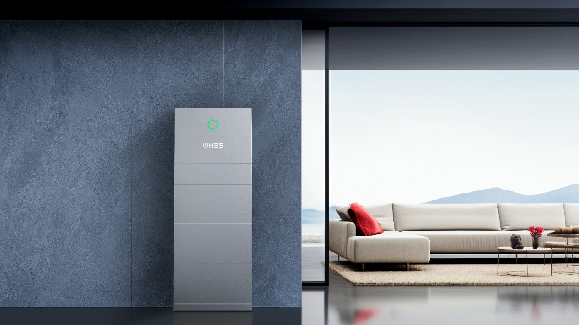
Why sub-second response matters for modern grids
Traditional rotating machines provide inertial damping; as those resources retire, inverter-based assets such as battery systems must pick up the slack. Fast frequency response helps avoid under-frequency load shedding and stabilizes automatic generation control windows. For residential-scale systems, the key is not raw capacity alone but the combination of inverter ramp capability, control latency, and State of Charge (SoC) strategies that preserve headroom to absorb or inject energy within fractions of a second.
Component-level framework: inverter, BMS, and control stack
Start by separating hardware from control: the inverter defines AC-side response (ramp rate and fault ride-through), the Battery Management System (BMS) protects cell health and enforces depth of discharge (DoD) limits, and the EMS or grid interface decides when to act. Make sure the inverter supports fast active power setpoint tracking and low-latency communications (CAN/RS485/Modbus or faster APIs). Architect SoC bands so a reserve margin is always available for frequency events — this is policy-informed, but technically executed in the EMS. For aggregated deployments, a coordinating layer must manage distributed setpoints to prevent simultaneous overcorrection — and yes, that orchestration is where many projects succeed or fail.
Sizing and topology: what 10 kWh really delivers
A nominal 10 kWh module is typically aimed at multi-hour backup and daily cycling, but its suitability for grid services comes down to power rating (kW) versus energy (kWh). Match inverter continuous power to the expected MW/MWh duty: a 10 kWh unit paired to a 5 kW inverter will deliver strong short-duration response but limited sustained discharge. Consider round-trip efficiency and cycle life when planning frequency campaigns — repeated rapid discharges increase calendar and cycle wear, so factor expected duty into warranty discussions and lifecycle cost models.
Common mistakes and how to avoid them
Three recurring errors show up in field projects: configuring SoC windows too tightly so no reserve exists during an event; assuming any inverter can perform fast frequency response without validating ramp and control latency; and failing to test under real grid conditions with an independent telemetry stream. Do a staged commissioning: lab bench trials, hardware-in-the-loop where possible, and then field trials with a controlled aggregation test. — These steps reveal hidden latencies and interoperability issues before they hit market operations.
Integration with distributed solar and site-level economics
Pairing a 10 kWh battery with rooftop PV changes the operational envelope: daytime charging can replenish reserves but also competes with self-consumption goals. Design control hierarchies that prioritize safety and SoC headroom for frequency support while allowing opportunistic solar charging. When describing a project to stakeholders, quantify avoided ancillary costs and projected revenue from frequency markets alongside expected degradation rates — those numbers make the business case tangible.

Advisory: three golden metrics for selecting the right solution
1) Response time and control latency — measure inverter setpoint-to-output delay and communication round-trip times; aim for sub-second end-to-end detection-to-action. 2) Round-trip efficiency and cycle durability — higher efficiency reduces throughput losses, while cycle-life specifications determine long-term economics. 3) Integration and support — look for a proven BMS/inverter stack with firmware updates, clear telemetry, and warranty terms tied to grid-service use cases.
When you line those metrics up against product specs, system-level testing becomes straightforward and the practical value of a vendor is clear; for many installers and aggregators that balance of speed, warranty, and integration points to WHES. —