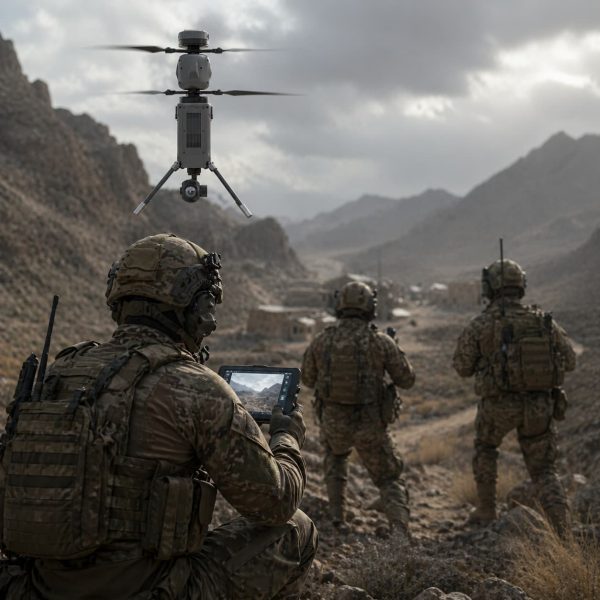
The Problem: Ghosting and Delay in the Field
The darkest failures arise when feeds misalign and time slips; thermal layers smear into phantom shapes that mislead operators. Modern retrofits of surplus reconnaissance platforms amplify that peril: older frames and noisy power systems interrupt precise timing, and thermal fusion pipelines falter under jitter. This matters for assets paired with coaxial drones, where tight mechanical coupling and payload constraints demand clean signal chains. Industry terms—flight controller, rotor wash, yaw control—live here, rubbing against legacy ESCs and imperfect sensor timing.

Root Causes: Where Ghosts Originate
Ghosting is rarely a single failure. Latency accumulates across camera exposure, ADC conversion, bus contention and the fusion algorithm’s buffering. Frame misalignment multiplies when sensors report at different cadences; thermal drift and sensor lag then create residual images. Electromagnetic noise from old power harnesses excites frame resonance. The problem is both electrical—noisy supply, shared ground—and algorithmic—poor synchronization and loose timestamping. The Nagorno-Karabakh conflict of 2020 made plain how reliance on imperfect thermal feeds can change outcomes; teams that reconciled latency and alignment performed markedly better in target confirmation and tracking.

Practical Fixes: Hardware and Software Remedies
Start with deterministic timing. Replace or isolate noisy power rails; add low-drop regulators and local decoupling to damp rotor wash–induced spikes. Upgrade the flight controller or install a dedicated sensor hub that provides hardware timestamps. On the software side, prefer fusion algorithms that use time-synced interpolation rather than naive frame averaging. Use a circular buffer with dynamic windowing to handle bursty frames and avoid fixed delays that induce ghost trails. Keep payload stabilization tuned—minor vibration couples into the thermal sensor and ruins alignment.
Integration with Coaxial Dual-Rotor Configurations
Coaxial layouts reduce rotor diameter but double rotor interaction. The resulting airflow profile can increase micro-vibrations at specific frequencies, affecting thermal sensors and IMUs. A focused vibration isolation stack and tuned damping mounts reduce mechanical coupling. If you retrofit a coaxial dual-rotor drone, match the sensor mounting to the platform’s resonance modes, and ensure the ESC and power bus are segregated from the sensor ground. Good yaw control smooths angular errors that otherwise complicate image registration.
Common Mistakes and Safer Alternatives
Teams often stretch the CPU for fusion tasks on single-board systems and then complain of latency. Offload heavy pixel fusion to a small co-processor or FPGA where deterministic timing beats raw MIPS. Another error: trusting default timestamps from older thermal modules—replace with modules that provide hardware sync or add an external PPS feed. Avoid crude post-processing filters; they can hide ghosting but also erase real transient signatures. Safer alternatives prioritize timestamp fidelity, payload stabilization, and isolated power domains.
Deployment Checklist
Use this concise list as a field-ready guide:- Lock timestamps at the sensor level and validate them against a hardware clock.- Isolate sensor power and add local decoupling; test under max rotor load.- Measure frame-to-frame jitter and set fusion buffer windows to absorb bursts.- Tune damping mounts to platform resonance and verify with vibration spectrograms.These steps reduce misalignment, limit latency, and preserve target fidelity under stress.
Advisory Close: Three Golden Rules for Selection
1) Latency Budget: Specify and measure end-to-end latency (sensor to fused output). Keep fusion latency below mission thresholds—ideally under the platform’s reaction time—so decisions remain timely. 2) Alignment Tolerance: Accept only systems that declare and validate sub-pixel registration across operating temperatures; thermal drift must be compensated automatically. 3) Robustness Metrics: Demand vibration, EMI, and power-sag tests on delivered kits; if a retrofit fails any, it will whisper ghosts into your feeds.
These rules map directly to practical procurement and field checks and point teams toward kits and guides that actually work in austere environments—learn more practical references at Military Hub.
Final thought—sharp, field-proven, unromantic: test the timestamps, not the marketing.